 |
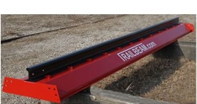 |
Railbeam type TN406 was developed in order to obtain a lighter construction, and at the same time were simple to maintain. In addition the width of the Railbeam increased from 600 to 800 mm, thereby reducing the amount of steel sheet below the Railbeams. To ease the transport of Railbeams, they are prepared in a lengths of 6 meters.
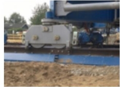
For type of TN406 used rail type S54 or UIC60. The rail is secured with special brackets.
For Railbeam spacers are used for ensuring constant gauge, additionally two types of end stops and a stop which electrically disconnects power on contact.
Joint of individual sections takes place by means of fishplates between the rails and bolts between the Railbeam sections.
Kran Elektro has prepared a guide to access the possible use of steel plates under the Railbeam. Calculation of the current case is presumed executed by construction engineering.
M0UNTING AND LAYING OF CRANETRACK MADE BY RAILBEAMS
The beam is designed for a corner pressure up to 1500 kN, with 2 wheel bogie.
The RAILBEAM is a welded beam after EU standard, and is CE-marked. RAILBEAMS are joined with 6x M24 bolts.
The rail is bolted to the beam at each 500 mm with M20 bolts.
The railbeam is for rail-going cranes and consists of a welded steel beam with mounted rail.
The railbeam is to be placed on a sustainable surface consisting of compressed stable gravel or macadam. Load capacity of at least 300 kN/m2 is calculated.
When building the base, the crown width on both sides must extend approx. 80 cm beyond the base plates.
At high loads, steel plates are placed under the railbeam to achieve sufficient load-bearing capacity.
The individual railbeams are assembled with brackets and bolts.
The Railbeams are equipped with lifting eyes for easy placement.
Safety equipment: Spacer roof that ensures constant track gauge. Electric end stop, sliding end stop and fixed end stop. The end stops are placed in that order.
Instructions on how to build.
The Railbeam must be placed on ground with sufficient capacity to carry the corner load from the crane.
Use gravel compressed to minimum 300 kN/m2 or use macadam.
Place the Railbeam by means of the lifting brackets.
When building the underlay be aware of the width of gravel under the railbeam, see drawing below.
To estimate base under the Railbeam, see Calculation/Base on top of this page.
The Railbeams are connected with a pair of fishplates between the rails and 6 bolts between the beams.
Security:
As the cranes local position is not known to us, we make certain reservations for capacity of soil and situations where strong wind will have influence on the cranes stability. With storm we recommend to anchor the crane.
By mounting Railbeams on steel plates it is recommended to place a material with higher friction coefficient between Railbeam and steel plate.
There are three types of end stops:
1. Electrical end stop: The electrical power is disconnected.
2. Sliding end stop: Will reduce the speed of the crane
3. Permanent end stop: This end stop is bolted to the rail.
The Railbeams shall be mounted by joining endplate to endplate with 6x M24 bolts.
Then the end stops are mounted to the rail.
Please note that no potholes under the steel plate can be accepted.